Digital Logic Question 1
a. Given a system that is described by the following equation:
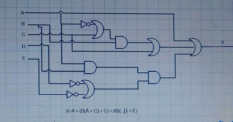
X = A + (B(Ā + C) + C) + AB(Ď+ Ē)
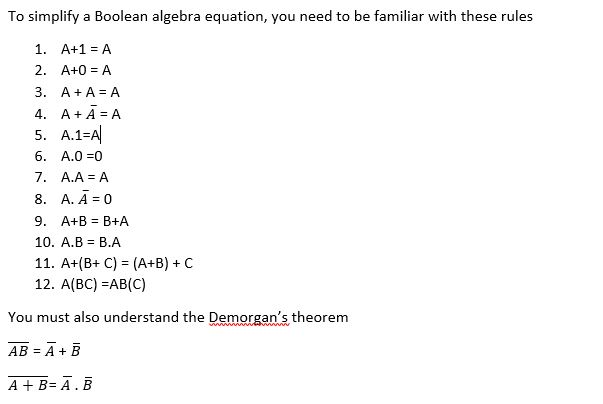
- Simplify the equation using Boolean algebra
- Implement the original and the simplified equation in “la” with a digital circuit
- Construct a truth table for the original equation
Solution
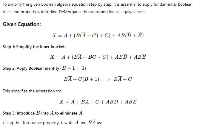
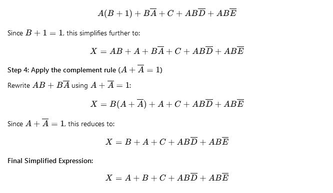
ii. LA diagram for the original equation
LA diagram for the simplified equation
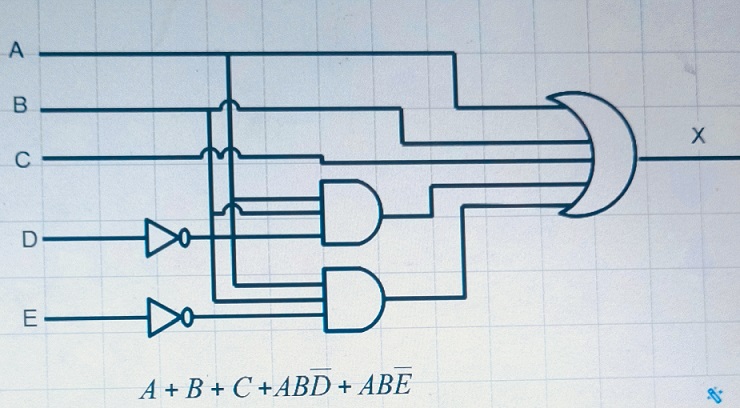
iii. construct a truth table for the original equation
More simplification Examples
F=AB+(AC)′+AB′C(AB+C)
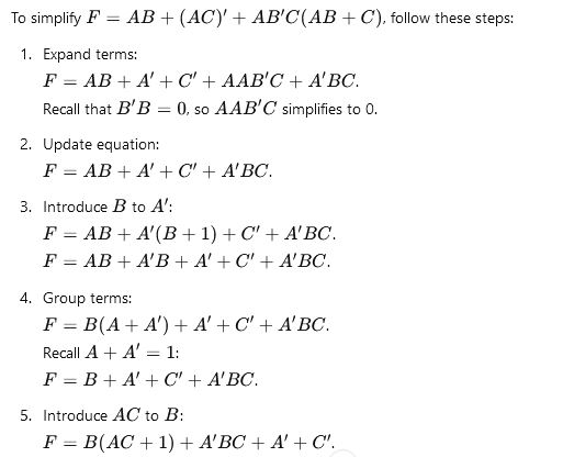
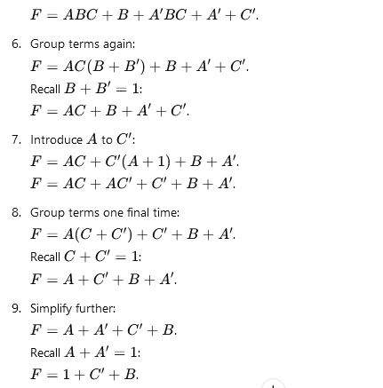
10. Finally, recall 1+C′=1 and 1+B=1 : F=1
Thus, F=1, as required (Q.E.D).
Try the following
- ABC + ABC’ +AB’C + A’BC
- X’ + XY + XZ’ + XY’Z
Digital Logic Question 2
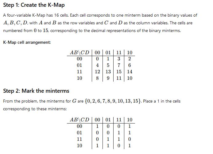
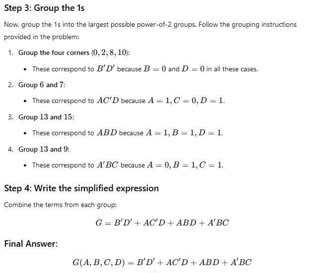
a.simplify the four variable function G(A,B,C,D) Σ(0,2,6,7,8,9,10,13,15) using the K-Map method. The numbers in the summation are the decimal representation of the minterms of G(where A represents the most-significant bit of the equivalent binary representation)
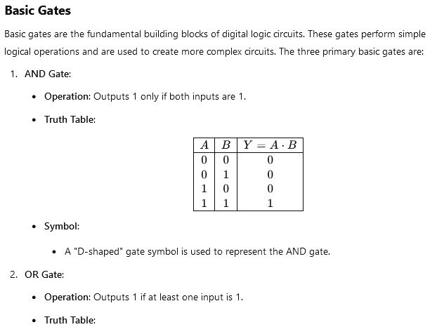
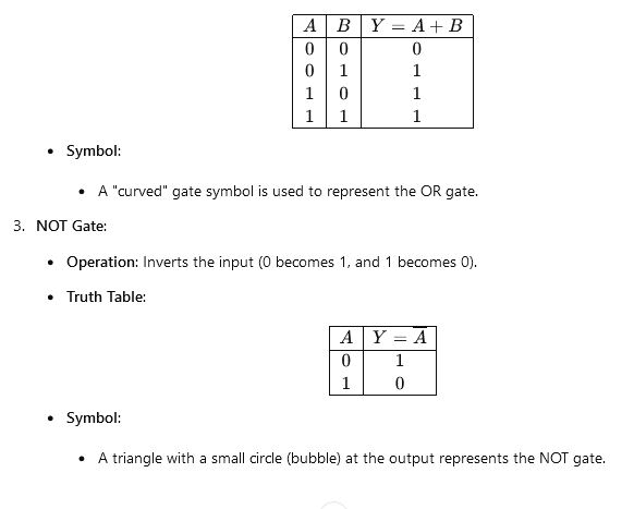
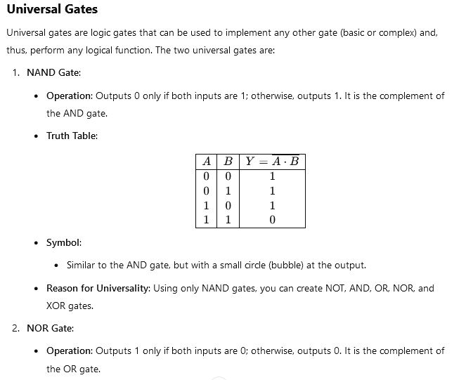
b. Distinguish between basic gates and universal gates with appropriates examples
c. Define XOR and XNOR gates with their truth tables
Solution
a. To simplify the four variable function G(A,B,C,D) Σ(0,2,6,7,8,9,10,13,15) using the Karnaugh map (K-map) method, let’s follow these steps:
b. Distinguish between basic gates and universal gates with appropriates examples
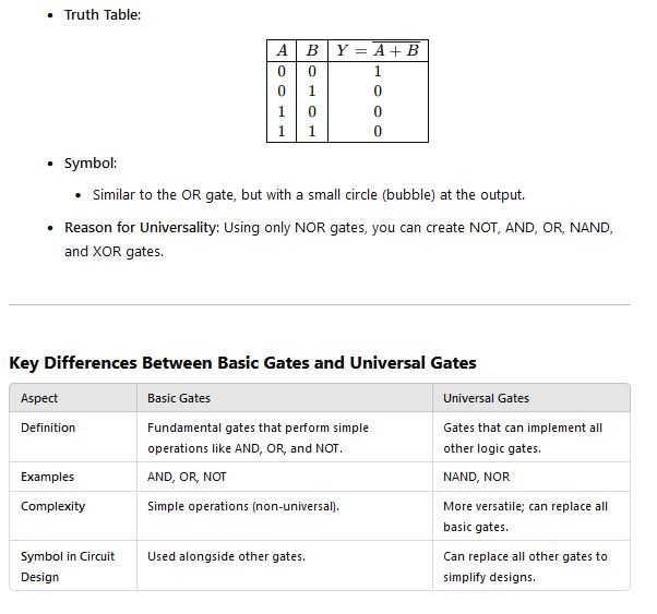
C. Define XOR and XNOR gates with their truth tables
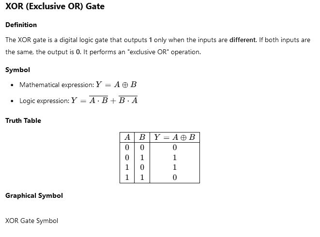
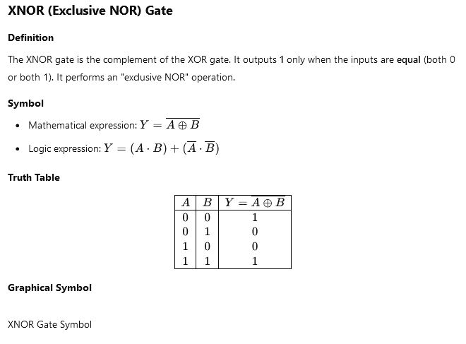

Digital Logic Question 3
3a. subtract the following numbers using two’s complement:
- 11110011-11000011
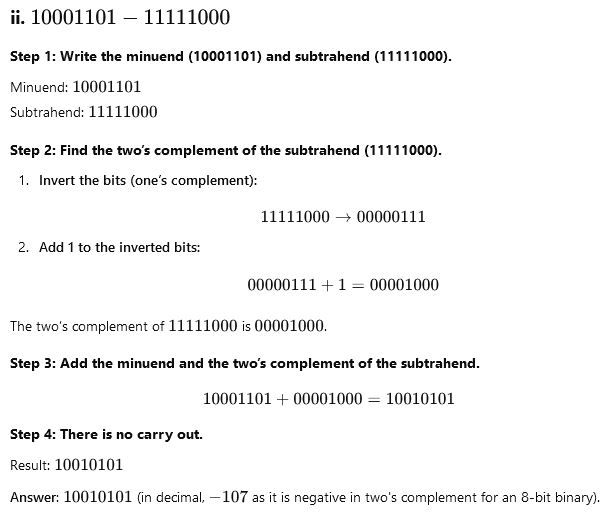
- 10001101-11111000
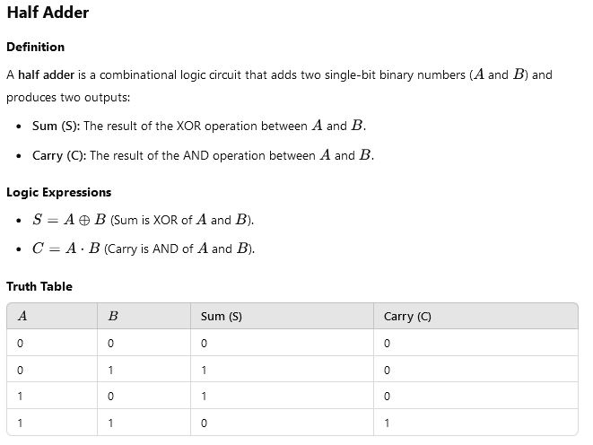
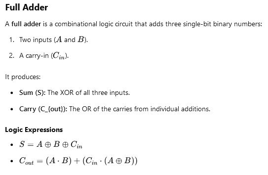
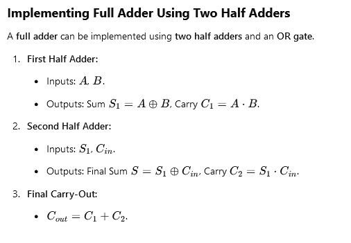
3b. Explain the half adder. Implement the full adder using two half adders.
3c. briefly describe the main feature of a combinational circuits.
Solution
3a. subtract the following numbers using two’s complement:
- 11110011-11000011
- 10001101-11111000
To perform subtraction using two’s complement, follow these steps:
- Write the minuend (first number) in binary.
- Write the subtrahend (second number) in binary.
- Find the two’s complement of the subtrahend:
- Invert the bits of the subtrahend (one’s complement).
- Add 1 to the inverted bits.
- Add the minuend and the two’s complement of the subtrahend.
- If there’s a carry out (extra bit), discard it. If not, the result is negative, and it’s already in two’s complement form.
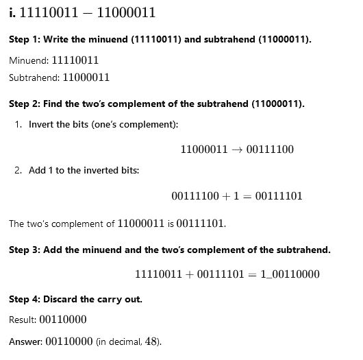
3b. Explain the half adder. Implement the full adder using two half adders.
3c. briefly describe the main feature of a combinational circuits.
Main Features of Combinational Circuits
- No Memory Elements
- Combinational circuits do not have memory, meaning their output depends solely on the current input values and not on past inputs.
- Direct Input-Output Relationship
- The output is calculated as a function of the inputs using logical operations (AND, OR, NOT, etc.).
- No Feedback
- Signals do not loop back from outputs to inputs, ensuring the circuit remains stable and predictable.
- Fast Operation
- Since there are no memory elements or feedback loops, the circuit processes inputs and produces outputs almost instantaneously.
- Implements Boolean Functions
- Combinational circuits are designed to perform specific Boolean logic functions, such as addition, subtraction, or data comparison.
- Examples of Use
- Common examples include arithmetic circuits (adders, subtractors), multiplexers, demultiplexers, encoders, and decoders.
Digital Logic Question 4
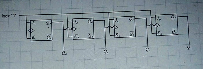
ai. Using J-K flip flops, draw the logic diagram of a 4-bit asynchronous binary up-counter
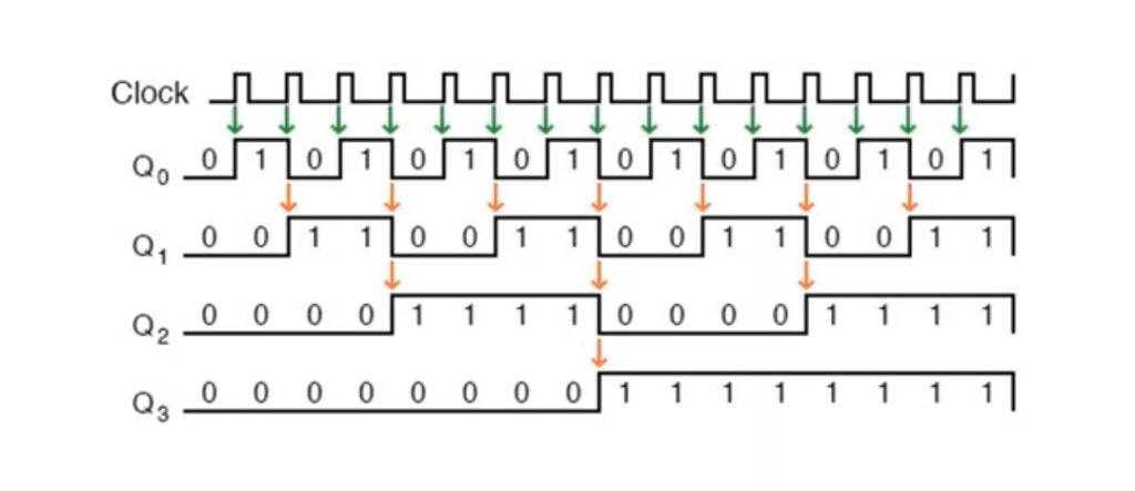
aii. Design a timing diagram for (4ai)
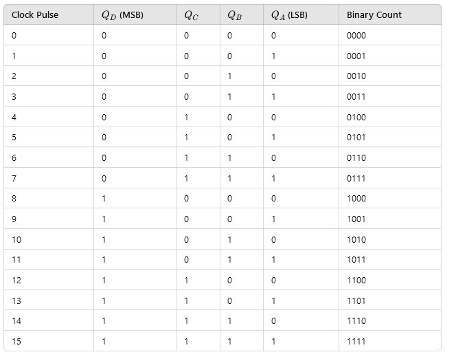
bi. Deduce the truth table for (4aii)
bii. Show diagrammatically the sequential logic representation
ci. What are digital counters
cii. Mention the typical application of digital counters
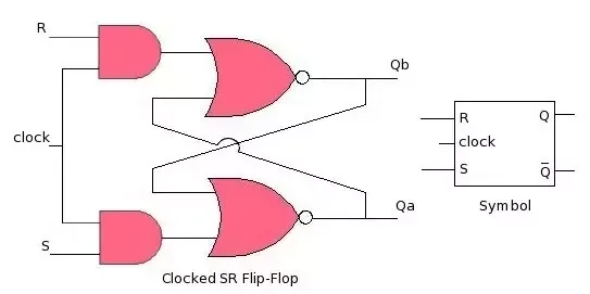
ciii. Illustrate, using logic diagrams am logic symbols the difference between clocked and the unclocked S-R fillip-flops
Solution
ai. Using J-K flip flops, draw the logic diagram of a 4-bit asynchronous binary up-counter
aii. Design a timing diagram for (4ai)
bi. Deduce the truth table for (4aii)
ci. What are digital Counters?
A digital counter is a sequential circuit that counts the number of clock pulses applied to its input. It operates using flip-flops as the basic building blocks, which toggle their states based on the clock signal. Digital counters are commonly used in digital electronics for counting, measuring time intervals, frequency division, or event monitoring.
Key Features of Digital Counters:
- Sequential Operation: Counters change their states in a defined sequence, depending on the clock pulses.
- Flip-Flops: Counters use flip-flops (e.g., J-K, T, or D flip-flops) as memory elements.
- Binary Representation: The state of the counter is usually represented in binary form.
- Asynchronous and Synchronous Counters:
- Asynchronous (Ripple) Counter: The flip-flops are triggered by the output of the previous flip-flop.
- Synchronous Counter: All flip-flops are triggered simultaneously by the same clock signal.
Types of Digital Counters:
- Up Counters: Count in ascending order (e.g., 0, 1, 2, …).
- Down Counters: Count in descending order (e.g., 7, 6, 5, …).
- Up-Down Counters: Can count in both directions (up or down).
- Modulo-N Counters: Reset after reaching a specified count (e.g., Mod-10 counter resets after 9).
cii. Mention the typical application of digital counters
- Timers: Used to measure time intervals.
- Frequency Counters: Measure the frequency of a signal.
- Digital Clocks: Keep track of seconds, minutes, and hours.
- Event Counters: Count occurrences of specific events (e.g., objects passing a sensor).
ciii. Illustrate, using logic diagrams am logic symbols the difference between clocked and the unclocked S-R fillip-flops

Time to Unleash Your Knowledge
🎓 Ready to show off your genius? 🤓 Hit the ‘Take Exam’ button below—after all, your brain has been on a study vacation long enough! 🌟 Go ahead, prove your brilliance! 💥


